| NXP MIMXRT1xxx-EVK Platform HAL | ||
|---|---|---|
 | Chapter 313. NXP MIMXRT1xxx-EVK Platform HAL |  |
Name
CYGPKG_HAL_CORTEXM_MIMXRT1XXX_EVK
— eCos Support for the IMXRT1050-EVKB and MIMXRT1064-EVK boards
Description
This document covers the configuration and usage of eCos on the NXP MIMXRT10XX-EVK evaluation kits. This includes the RT1052 and RT1064 on which this support has been tested. Boards containing other devices in the RT10XX family should be supportable with minimal effort.
For typical eCos development it is expected that programs will be downloaded and debugged via a hardware debugger (JTAG/SWD) attached to either the standard ARM 20-pin JTAG connector or via the on-board CMSIS-DAP USB socket. Use of a hardware debugging interface avoids the requirement for (and cost overheads of) a debug monitor application to be present on the platform.
![[Note]](pix/note.png) | Note |
|---|---|
As shipped the EVK boards are configured for H/W debugging
via the onboard CMSIS-DAP interface. If the standard ARM
20-pin 2.54mm IDC |
The Startup
section below gives an overview of the various
STARTUP types that can be configured. The
selected STARTUP type defines where the
final application binary will be linked to execute from, as
well as control some run-time features of the final
application (e.g. standalone or dependant on a ROM monitor,
etc.).
Supported Hardware
The variant HAL includes support for the on-chip serial devices which are documented in the variant HAL. LPUART1 is connected to the CMSIS socket where it is available as a CDC/ACM interface. There is no support for hardware flow control in this device. LPUART1 is configured as the default diagnostics console.
Device drivers provide support for the I²C interfaces, which are instantiated by the platform (PLF) HAL. These have been tested using external I²C devices.
Device drivers provide support for the SPI interfaces, which are instantiated by the platform HAL. These have been tested using external SPI devices.
Support is available for the FlexSPI controller(s) with attached QSPI device(s). In the case of the MIMXRT1064-EVK board this support is provided for the SiP QSPI device as well as the external ISSI IS25WP064D QSPI device. For the IMXRT1050-EVKB the FlexSPI support requires board modifications to use the on-board QSPI ISSI IS25WP064D device in place of the default HyperFlash device.
Normally the first few blocks of the bootable QSPI NOR flash
are set aside for a bootable application image
(e.g. standalone SRAM application,
2nd-level boot loader, or a (RBSRAM)
RedBoot debug monitor image). The bootable application image
requires specific descriptor structures to be prefixed to
allow the i.MX RT ROM Bootloader to start the
application, as documented in the
flashimg_rt10
section. When using RedBoot (either a directly booted
RBSRAM build, or a
RBRAM build loaded via
BootUp or a
RBSRAM RedBoot), the last couple of blocks
of the flash device are used to hold the RedBoot
fconfig and FIS information. The
remaining blocks are free for use by application code. When
not using RedBoot all of the flash beyond the i.MX RT
ROM Bootloader required (DCD+image) is available for
application use.
![[Warning]](pix/warning.png) | Warning |
|---|---|
The It is important to power the board via an external PSU via J2, with the J1 pins 1-2 connected as appropriate if CAN, USB or Ethernet are to be used. |
Support for USB host and peripheral mode is provided by EHCI drivers. Host mass storage and CDC-ACM class drivers are present. The peripheral port is configured by default to provide a CDC-ACM device.
Support for Ethernet and CAN (not CAN-FD) is provided by configuring the respective device drivers.
| Note |
|---|---|
The |
Tools
The board port is intended to work with GNU tools configured for an arm-eabi target. The original port was done using arm-eabi-gcc version 7.3.0e, arm-eabi-gdb version 8.1, and binutils version 2.30.
flashimg_rt10
The i.MX RT ROM Bootloader will only bootstrap
applications prefixed with headers describing the
application to be started. A suitable bootable image
can be created using the
flashimg_rt10 tool to prefix the eCos
executable binary with the required descriptors.
The tool will by default create an image suitable to be booted from an SDcard.
To create a QSPI boot image from a binary image the
--qspi command-line option should be
used:
$ flashimg_rt10 --qspi image.bin qspi_boot.bin | Note |
|---|---|
Only binaries linked to execute from the On-Chip SRAM are supported as bootable applications. |
Application Boot Location Examples
For the mimxrt1050_evk and
mimxrt1064_evk targets the code executed
at boot can be loaded from flash using the ROM Bootloader
FlexSPI NOR flash support. Refer to the NXP H/W board
documentation and relevant i.MX RT Processor Reference
Manual for details on the available boot-from-reset
configurations.
The following section just highlights where images are stored in the FlexSPI NOR for some, common, example startup configurations.
| Note |
|---|---|
The following examples are not exhaustive. For example, a custom second-level bootloader can be used to start an application. These are just common examples. |
For FlexSPI configured boots the
mimxrt1050_evk target only has the
FlexSPI1 flash mapped from address
0x60000000. However, the FlexSPI boot
option for the mimxrt1064_evk can only
boot from the FlexSPI2 (SiP) flash mapped from address
0x70000000, but any second-level boot
loader or application started has access to the external
FlexSPI1 flash mapped from 0x60000000.
If an application binary is linked for SDRAM execution
then it needs to be loaded via a second-level boot
loader. Only the second-level bootloader (as started by
the i.MX RT ROM Bootloader) needs to be created
using the flashimg_rt10 tool. The
final application does not need to be converted. When
using BootUp as
the second-level boot loader the SDRAM application stored
in NVM will be a simple, raw, binary located at a
fixed location. When using
RedBoot as the second-level loader the application image
stored in the NVM will be the larger ELF image, with FIS
controlling where the image is located.
In the following figures BLUE is used to indicate an image at its storage location, with GREEN indicating an application at its final execution location. For applications that can be loaded via a RedBoot debug session YELLOW is used.
Direct standalone application startup
If the final application loads and executes from On-Chip
SRAM, or is itself a second-level boot loader executing
from SRAM then the suitable wrapped (QSPI bootable) image
is placed from offset 0 of the
respective bootable flash device.
The following figures highlight the RT1064 and RT1052 locations.
Figure 313.1. Standalone mimxrt1064_evk SRAM application
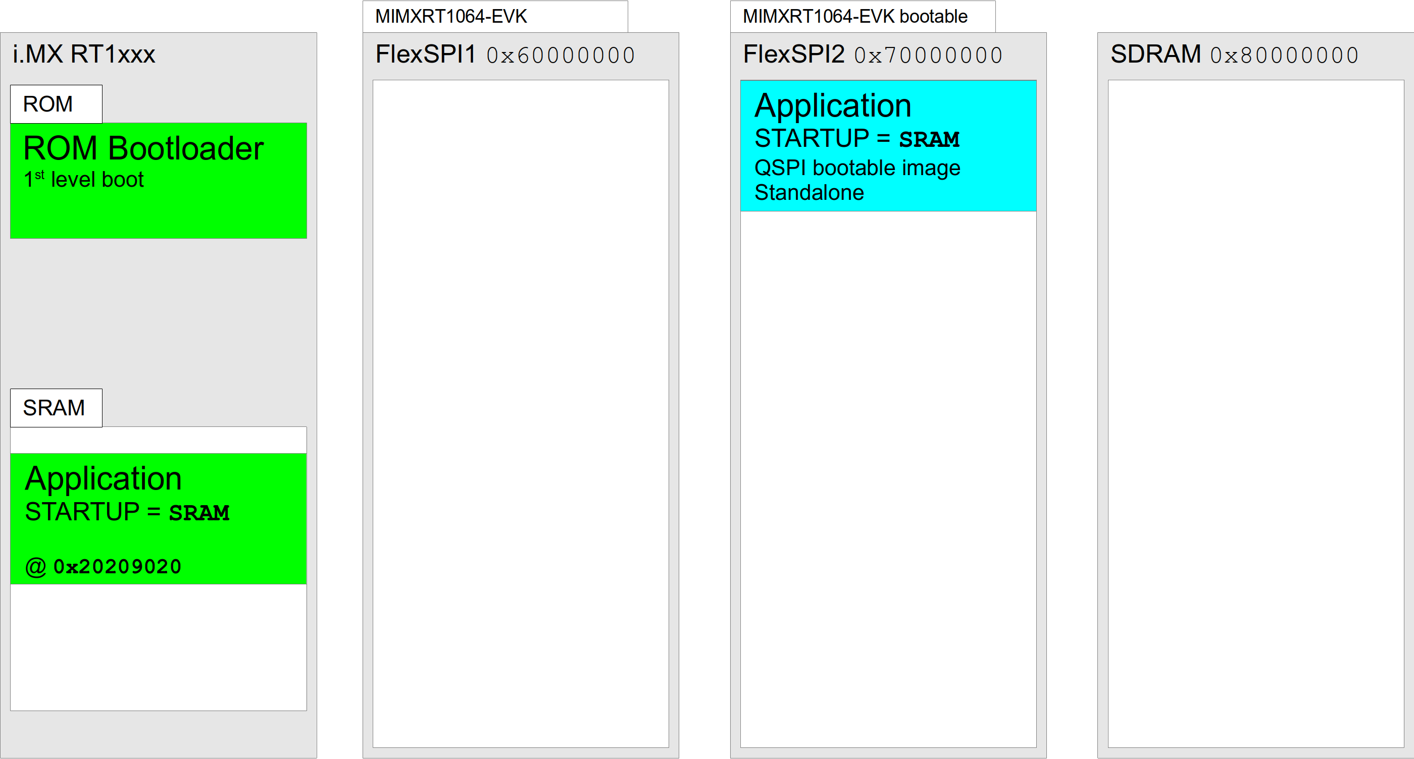
Figure 313.2. Standalone mimxrt1050_evk SRAM application
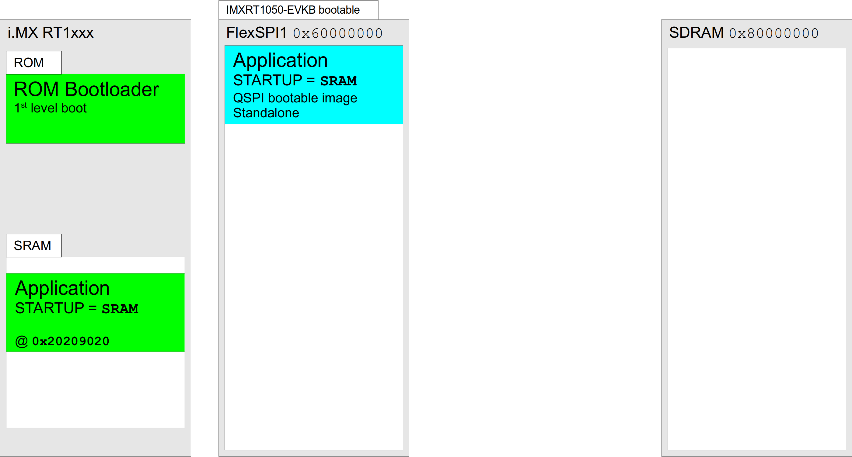
Since the RedBoot specific RBSRAM is
just a variation of a SRAM application, for the figures
above we can replace the SRAM
Application with a RBSRAM RedBoot QSPI
bootable image. Examples of which are shown below.
BootUp used to start application
For systems where a standalone, external-SDRAM, application is to be started at boot then the BootUp second-level boot loader can be used.
Normally the final application would be a
JSDRAM startup application as shown for
the RT1064 and RT1050 platforms respectively.
Figure 313.3. Standalone mimxrt1064_evk JSDRAM application
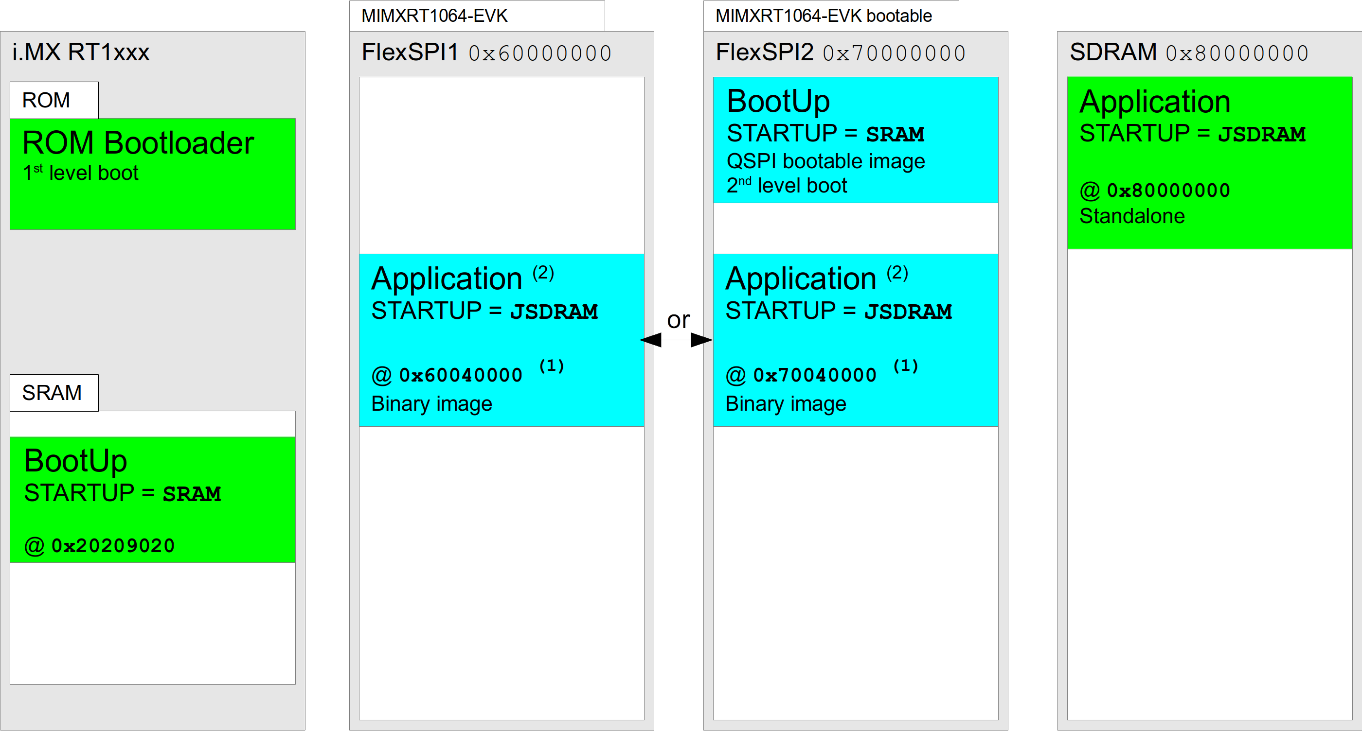
(1) address shown is the result of adding the
default
CYGNUM_BOOTUP_IMX_SOURCE_OFFSET
offset onto the relevant
FlexSPI# flash base
|
(2) default
CYGIMP_BOOTUP_IMX_SOURCE is
FlexSPI2, but BootUp can use FlexSPI1 if required
|
Figure 313.4. Standalone mimxrt1050_evk JSDRAM application
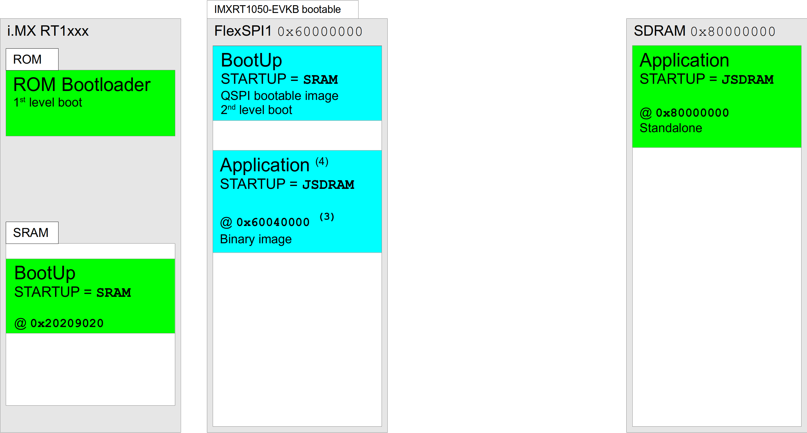
(3) address shown is the result of adding the
default
CYGNUM_BOOTUP_IMX_SOURCE_OFFSET
offset onto the FlexSPI1 base address
|
(4) CYGIMP_BOOTUP_IMX_SOURCE is FlexSPI1
|
However, if a SDRAM based RedBoot is required
(RBRAM startup) then BootUp can be used
to load and start the SDRAM RedBoot, which can then
subsequently be used to load RAM
startup applications that make use of RedBoot
functionality via the virtual vector support. The
following figures highlight that the SDRAM configured
RedBoot requires a second-level boot loader to copy and
start the RedBoot instance from SDRAM:
Figure 313.5. Standalone mimxrt1064_evk RBRAM application
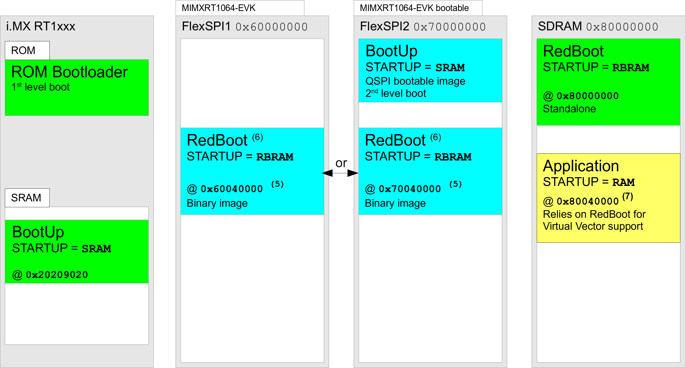
(5) address shown is the result of adding the
default
CYGNUM_BOOTUP_IMX_SOURCE_OFFSET
offset onto the relevant
FlexSPI# flash base
|
(6) default
CYGIMP_BOOTUP_IMX_SOURCE is
FlexSPI2, but BootUp can use FlexSPI1 if required
|
(7) default
CYGMEM_REGION_redboot_SIZE
offset into SDRAM defined in the
“mlt_mimxrt1xxx_evk.h”
header with app loaded by RedBoot from FIS or via
GDB stubs
|
Figure 313.6. Standalone mimxrt1050_evk RBRAM application
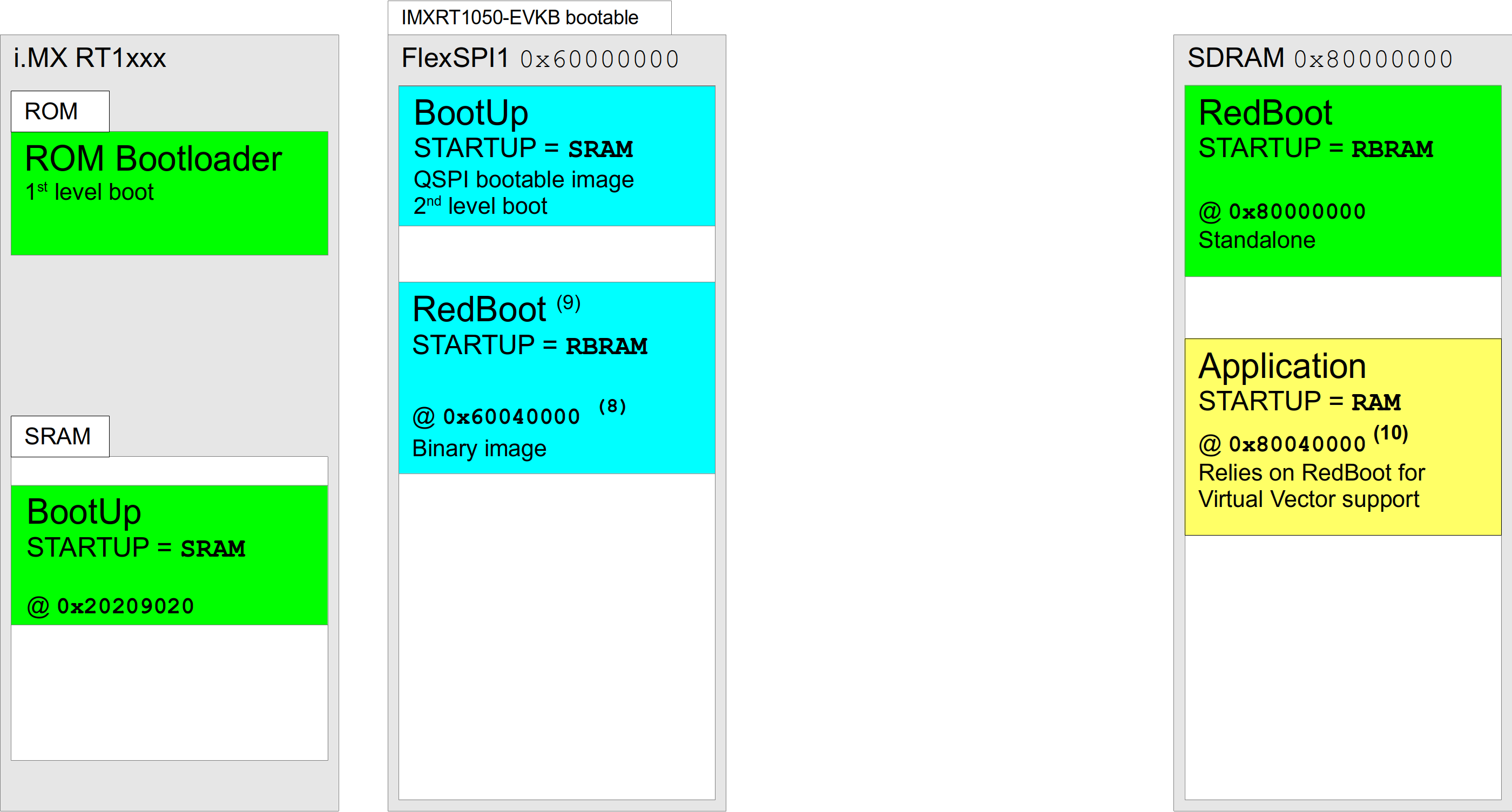
(8) address shown is the result of adding the default
CYGNUM_BOOTUP_IMX_SOURCE_OFFSET
offset onto the FlexSPI1 flash base
|
(9) CYGIMP_BOOTUP_IMX_SOURCE is
FlexSPI1
|
(10) default
CYGMEM_REGION_redboot_SIZE
offset into SDRAM defined in the
“mlt_mimxrt1xxx_evk.h”
header with app loaded by RedBoot from FIS or via
GDB stubs
|
RedBoot used to start application
When RedBoot is being used to load an application, the
storage location of the ELF image held in flash is
controlled by the RedBoot FIS support. The following
figure shows a SRAM based RedBoot setup, but the same FIS
held ELF image is also applicable to external-SDRAM
(RBRAM) RedBoot instances.
Only the RT1064 platform is shown in the figures below, but as per the standalone SRAM examples above, for the RT1052 based target the bootable second-level loader image and stored application image will be held in the FlexSPI1 flash memory.
Figure 313.7. mimxrt1064_evk SRAM RedBoot and RAM application
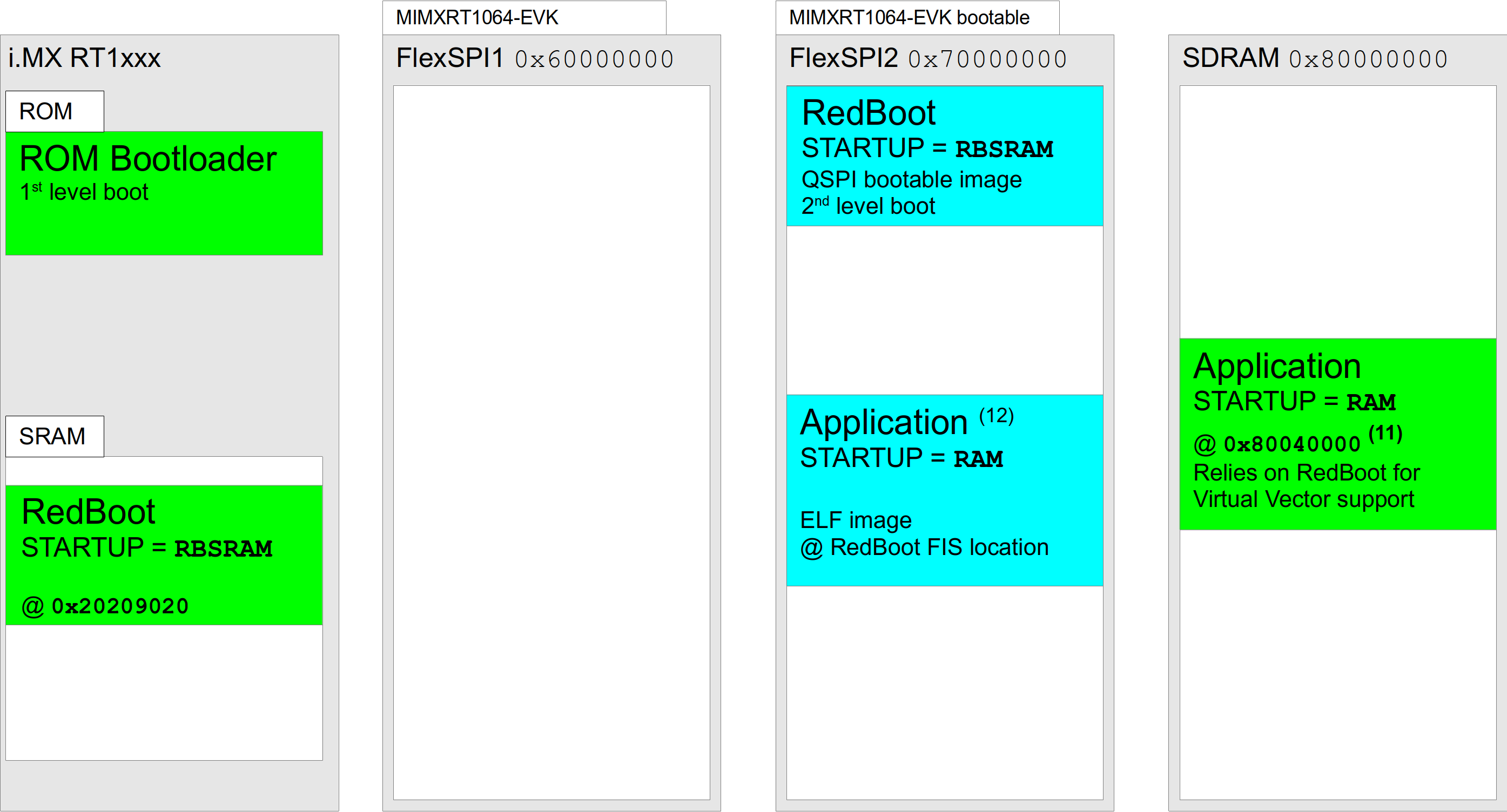
(11) address shown is the result of adding the
default
CYGMEM_REGION_redboot_SIZE
offset onto the SDRAM base address, where that
offset manifest is defined in the
“mlt_mimxrt1xxx_evk.h”
header, and the app subsequently loaded by RedBoot
from FIS or via GDB stubs
|
| (12) figure shows RedBoot managed application stored in flash, but app can also be loaded via the GDB stubs debug connection |
Figure 313.8. mimxrt1064_evk SRAM RedBoot and JSDRAM application
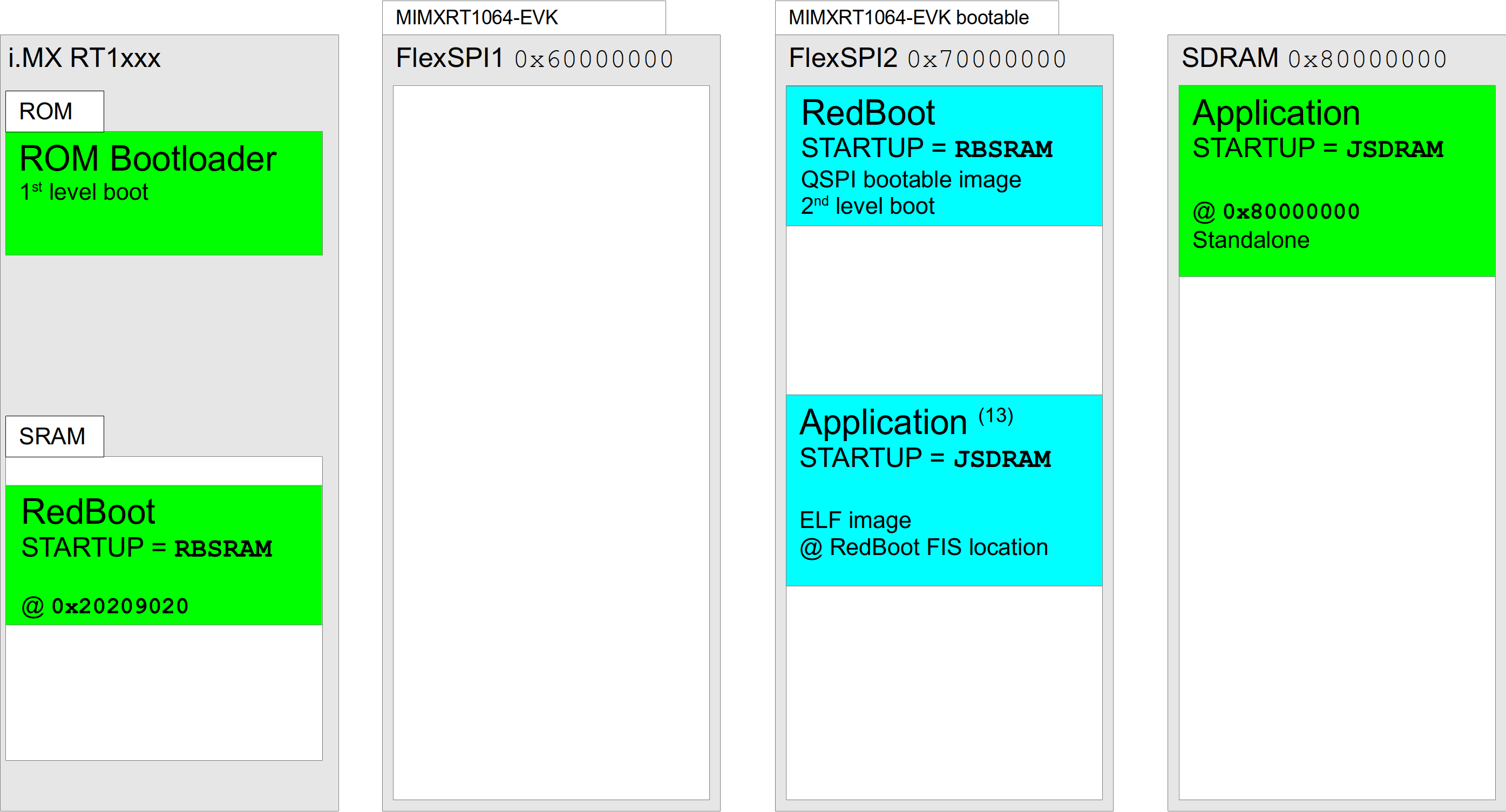
| (13) figure shows RedBoot managed application stored in flash, but app can also be loaded via the GDB stubs debug connection |
| |  | |
| Chapter 313. NXP MIMXRT1xxx-EVK Platform HAL |  | Setup |
| 2024-03-18 | Open Publication License |