| Setup | ||
|---|---|---|
 | Chapter 280. Atmel SAMA5D3 Xplained Platform HAL |  |
Name
Setup — Preparing the SAMA5D3-XPLD Board for eCos Development
Overview
In a typical development environment, a direct hardware JTAG
connection is used to load and execute the eCos application. For
hardware debugging, eCos applications would normally be configured
for ROMRAM startup. The same application binary can
be executed via a hardware debugger environment, or programmed into
the onboard NAND flash for loading via a second-level boot loader.
Alternatively, the SAMA5D3-XPLD board can boot from NAND flash into
a ROMRAM RedBoot. eCos applications are then
configured for RAM startup and then downloaded and
run on the board via the debugger arm-eabi-gdb.
![[Note]](pix/note.png) | Note |
|---|---|
Unless you explicitly need network based debugging, are interested in other aspects of the RedBoot functionality, or you lack the requisite hardware support, it is generally the case that development and debugging using a direct hardware JTAG/SWD approach is generally superior and obviates the need to install RedBoot on the target.
Atmel Secure Boot code and the normal
For JTAG debugging the |
Bootstrap process
The typical bootstrap process for this board has several steps:
- RomBOOT (on-chip, cannot be modified).
- eCosPro BootUp or AT91Bootstrap
- Your choice of
ROMRAMeCos application (such as RedBoot).
For more information about the bootstrap process, refer to the CPU variant bootstrap overview.
RedBoot Installation
The following RedBoot configurations are supported:
| Configuration | Description | Use | File |
|---|---|---|---|
| ROMRAM | RedBoot running from external RAM. Loaded from NAND by second-level boot loader, or directly via JTAG hardware debugger. | redboot_ROMRAM.ecm | redboot_ROMRAM.bin |
| Note |
|---|---|
The DBGU diagnostic (serial) debug channel is only exposed as TTL on J23 pins. A RS232 TTL to USB adapter can be used to allow serial diagnostic output. The serial terminal connection is not required for normal Ethernet based GDB debugging, but for initial board bring-up where no valid flash configuration is available it can be easier to see what network address has been supplied to the board.
If the standard serial diagnostic/terminal is not available, then it
is worth considering configuring the local DHCPD to present a known
(fixed) IP address. The current fixed RedBoot MAC address
is |
Programming RedBoot
There are several ways to program the target flash:
- Some hardware debuggers will allow direct programming of the target NAND flash.
-
If a hardware debugger is available but does not support NAND flash,
it is possible to load and run a
ROMRAMexecutable that does know how to write the image to its flash destination. - Atmel provides tools to work in conjunction with the on-chip SAM-BA monitor that can also be used to program the various memories. Detailed instructions for this process are provided in the Installing binaries with SAM-BA section.
| Note |
|---|---|
RedBoot is configured by default with both network interfaces active, and waits for both of them to come up before allowing user interaction. This may take up to a minute if either are not connected to a network. It is recommended to connect both interfaces. |
Initializing RedBoot Flash Configuration
When RedBoot is loaded into the on-chip flash, it maintains a number of persistent settings in the configuration store on the NAND flash. The flash configuration area needs to be initialized with the following commands.
RedBoot>fconfig -iInitialize non-volatile configuration - continue (y/n)?yRun script at boot: false Use BOOTP for network configuration: true Default server IP address: DNS domain name: DNS server IP address: Network hardware address [MAC] for eth0: 0x0E:0x00:0x00:0xEA:0x18:0xF0 Network hardware address [MAC] for eth1: 0x0E:0x00:0x00:0xEA:0x18:0xF0 GDB connection port: 9000 Force console for special debug messages: false Network debug at boot time: false Default network device: at91_eth1 Update RedBoot non-volatile configuration - continue (y/n)?y... Erase from 0x00000000-0x00000fff: . ... Program from 0x2fdff000-0x2fe00000 to 0x00000000: . RedBoot>
Rebuilding RedBoot
| Note |
|---|---|
Pre-built RedBoot binary images are supplied with the eCos release in
the |
RedBoot will normally be a ROMRAM startup, since it
will be loaded via the second-level bootloader, or loaded directly
using a hardware JTAG debugger, into the DDR2-SDRAM memory for
execution.
The following example illustrates the command-line steps needed to
configure and build a ROMRAM RedBoot:
$mkdir redboot_ROMRAM$cd redboot_ROMRAM$ecosconfig new sama5d3xpld redboot$ecosconfig import $ECOS_REPOSITORY/packages/hal/arm/cortexa/sama5d3/sama5d3xpld/current/misc/redboot_ROMRAM.ecm$ecosconfig resolve$ecosconfig tree$make
The RedBoot Location
section of the generic SAMA5D3 variant documentation provides a
graphical representation of the ROMRAM model.
Building BootUp
Full details are provided in the BootUp Integration section.
Building AT91Bootstrap
As an alternative to the eCosPro BootUp second-level loader,
the Atmel AT91Bootstrap second-level loader can be used to load
a ROMRAM startup type application from the NVM boot
memory into RAM for execution.
A version of the AT91Bootstrap source, modified by eCosCentric, is available in
the
directory $ECOS_REPOSITORY/packages/hal/arm/cortexa/sama5d3/var/current/misc/at91bootstrap.
The original (as of writing) is v3.6.2 obtained by:
git clone https://github.com/linux4sam/at91bootstrap
The modifications provide example configurations to allow RedBoot to be loaded by the SAMA5D3X-EK and SAMA5D3 Xplained platforms, and to allow compilation using the eCosCentric cross-compilation tools (e.g. 4.7.3e release).
The AT91Bootstrap binary can be built from the provided source with the following steps:
cd at91bootstrap
make mrproper
make sama5d3_xplainednf_redboot_defconfig
export CROSS_COMPILE=arm-eabi-
make
The result of this process is a second-level boot loader binary
binaries/sama5d3_xplained-nandflashboot-uboot-3.6.2.bin
that can be installed into NAND using SAM-BA as described below.
Installing binaries with SAM-BA
A version of the Atmel SAM-BA tool which supports
the at91sama5d3x-xplained target (e.g. v2-12 patch
level 7) can be used to install your choice of BootUp, AT91Bootstrap,
RedBoot or any other ROMRAM eCos application.
- Download and install the SAM-BA tool, plus any required patches, from http://www.atmel.com/tools/atmelsam-bain-systemprogrammer.aspx
- Disconnect JP5 (
NAND CS) and ensure no bootable SD card is installed - Connect host to J6 USB-A
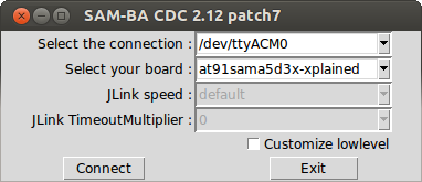
Launch the SAM-BA application
- Select the relevant COM or /dev/ttyACM port
- Select board type “at91sama5d3x-xplained”
- Hit “Connect”
Figure 280.1. SAM-BA Board Connection
- Re-connect (close) JP5
NAND CS Select
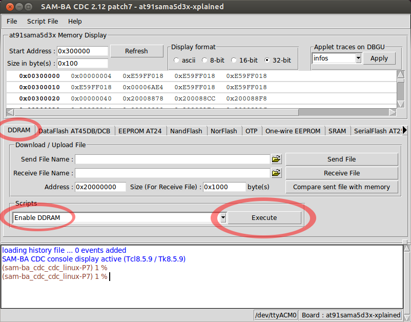
DDRAMtabIn “Scripts” select
Enable DDRAMand hitExecuteFigure 280.2. Enabling DDRAM
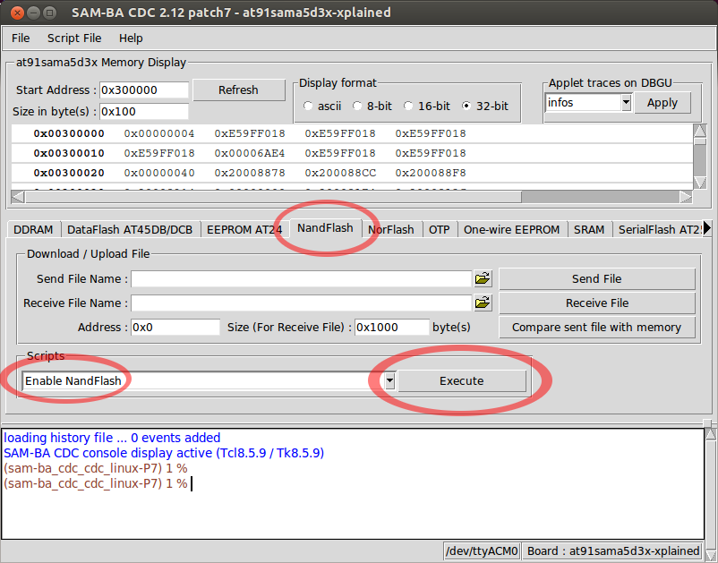
Select
NandFlashtab- In “Scripts” select
Enable NandFlashand hitExecute - In “Scripts” select
Enable OS PMECC parametersand hitExecute
Figure 280.3. Enabling NAND
- In “Scripts” select
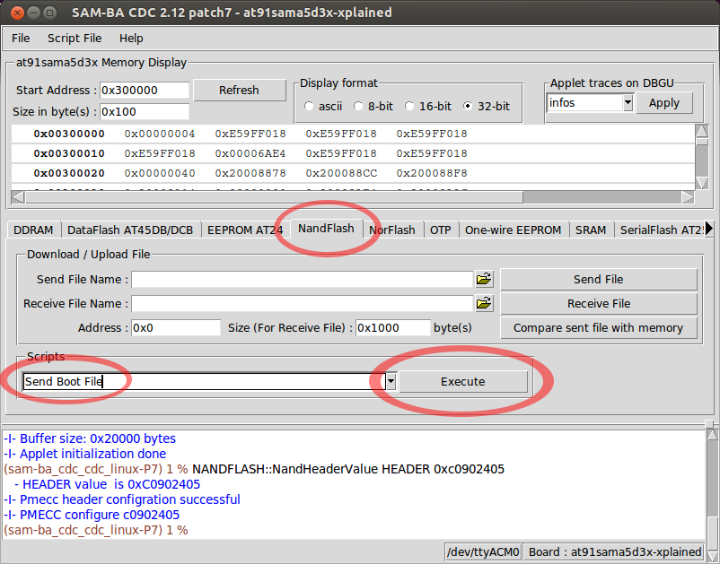
Program your choice of second stage bootstrap (BootUp or AT91Bootstrap):
Still within the
NandFlashtab, in “Scripts” selectSend Boot Fileand hitExecute-
A file selection dialog opens.
Find and select the relevant binary (e.g.
bootup.bin) and hitOpen.
-
A file selection dialog opens.
Find and select the relevant binary (e.g.
Figure 280.4. Programming the Second-Stage bootstrap
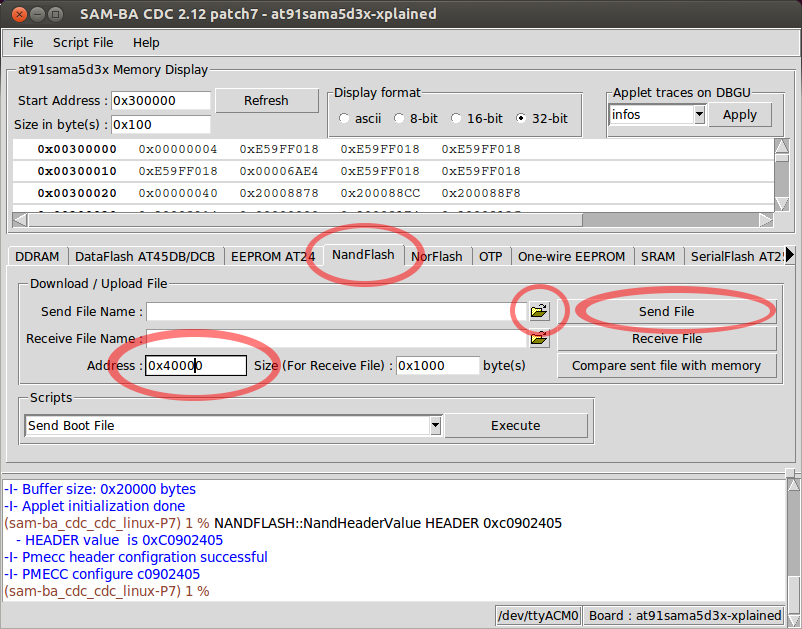
Program RedBoot (or other application)
Still within the
NandFlashtab, in the “Download/Upload File” area, select the file selection icon beside the
 Send File Name:field.A file selection dialog opens. Find and select the binary (e.g.
redboot.bin).![[Tip]](pix/tip.png)
Tip The
objcopytool may be used to convert a builtROMRAMeCos application to the binary format required for programming.arm-eabi-objcopy -O binary application.elf application.bin
In the “Address” field change the address to
0x40000.Note If you are using BootUp with a non-default setting of
CYGNUM_BOOTUP_SAMA5D3_SOURCE_OFFSET, use that value instead of0x40000.- Hit the
Send Filebutton.
Figure 280.5. Programming the Application
- The SAM-BA application can now be quit
Reset the board. The new images will be booted.
Note With RedBoot, the board will typically take several seconds to become ready as it waits for the network interfaces to initialise. (This may take up to a minute if either or both network interfaces are not connected to a network.) During this time RedBoot will not respond, either to telnet on the configured gdb port (usually 9000), or to input on the TTL debug channel. However the TTL debug channel will emit diagnostic output along these lines:
RomBOOT
+NAND: onboard: 1 partition  configured
NAND: Read partition geometry from config store
NAND: onboard: 2 partitions configured
Ethernet eth1: MAC address 0e:00:00:ea:18:f0
IP: 172.20.45.204/255.255.255.0, Gateway: 172.20.45.1
Default server: 172.20.45.29
DNS server IP: 172.20.45.29, DNS domain name: null

RedBoot(tm) bootstrap and debug environment [ROMRAM]
Non-certified release, version UNKNOWN - built 11:43:08, Jan 16 2015
| |  | |
| SAMA5D3 Xplained Platform HAL |  | Configuration |
| 2024-03-18 | eCosPro Non-Commercial Public License |